Intro
I’ve always wanted to create an RGB LED logo from scratch using my 3D printer and some parts from AliExpress, but I never found the time to actually build one, until now.
Table of Contents
3D Design
To start off, let’s first take a look at the finished product.
My first challenge was deciding which logo to use. Initially, I wanted to create a logo for my new site, wimpytuts.com, but I hadn’t even started designing that logo yet. So instead, I decided to go with the logo of my employer.
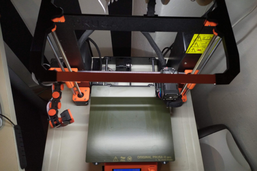
Before ordering any parts, the first step was designing the 3D-printed model. Based on its dimensions, I could then determine which components I needed to order.
Fusion 360
The very first step here was designing a 3D model that could properly house the LEDs. One important thing to keep in mind is that the LEDs are 5 mm wide. This means the inside of the letters at their narrowest points also needed to be at least 5 mm wide.
To find the font used in the original logo, I came across a handy website that allows you to upload an image and identifies the font used. This gave me exactly the font I needed, which I could then use in Fusion 360 to recreate the logo.
I created a new sketch and measured the narrowest points of the letters using the Inspect tool (the i button) in Fusion 360.
Once that was done, I offset the outer edges of the letters by 2 mm and extruded them to a height of 10 mm. I then embossed the top edges to give them a rounded look, for aesthetic purposes.
On the inside, I applied a 0.5 mm offset and raised it by 8 mm. This is because I plan to use 1 mm thick white inserts on top, allowing the LEDs to shine through evenly.
Finally, I added an additional offset of 6mm on the outside so the letters would fit into a separately printed backplane holder. Extruded it 4mm, and voilà this was the result.
Fitting the LEDs
I initially started by cutting the bendable LED strip into smaller sections, placing them inside each letter, and pulling the VDD, GND, and signal wires through the holes I had designed into the 3D model. However, this quickly turned into a mess.
Wires were stripped from the LED strip due to excessive tension, some wires blocked the light from the LEDs, and at one point my soldering iron even melted part of the printed letters. Clearly, this approach wasn’t ideal.
So I changed tactics. Instead, I cut one long LED strip and routed it through the entire logo from start to finish. This turned out to be a much cleaner and more reliable solution. That’s what I ended up using.
Build plate restriction
Because the smallest internal gap in the design is only 5 mm, the overall size of the logo ended up being too large to print in a single piece. As a result, I had to split the model into two parts, separating it between the letters M and B.
Once all the LEDs are in place, the 1 mm top plates can be installed. These act as a diffuser for the light coming from the LEDs.
The finished product, when turned off, looks something like this.
Electronics
With the 3D-printed parts finished, it was time to focus on the electronics needed to make everything work. Fortunately, there are many open-source projects that already solve this problem. One project in particular that caught my eye was WLED.
I created a bill of materials for every component I’ve used.
BOM
A list of the materials i’ve used for this project
- WLED Controller ESP8266 (Regular WLED)
- WLED Controller ESP32 (Moon Modules WLED)
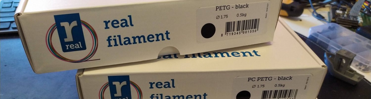
- Bendable RGB LED Strip
- i2s Microphone INMP441 (optional)
- Heat inserts (M3)
Software
Download
Like mentioned earlier there is a project called WLED and then there is the fork called WLED Moon Modules. I wanted to create custom effects and some other addons in the future like letting the LEDs react to audio, so i went for the latter instead.
Stick to the ESP8266 controller and the regular WLED project if you don’t need custom effects or microphone actions. The flash procedure and web interface are identical but the Moon Modules project (which is based on the regular WLED project) has these extra features build in.
As mentioned earlier, there is the original WLED project, as well as a fork called WLED Moon Modules. I wanted the ability to create custom effects and potentially add features later, such as audio-reactive lighting so I chose the Moon Modules version.
If you don’t need custom effects or microphone support, you can safely stick with the ESP8266 controller and the regular WLED project. The flashing procedure and web interface are identical, but the Moon Modules project (which is based on standard WLED) includes these extra features out of the box.
Head over to the project’s GitHub page and download the latest build:
WLEDMM_14.5.0-beta_esp8266_4MB_M.bin
(This is the image required for the WLED ESP8266 ESP-12S board)
pip install esptoolInstall
Once the image has been downloaded, we can begin by erasing the flash memory using esptool. Before doing this, the board must be placed into boot mode by temporarily connecting GPIO0 to GND.
With the board in boot mode, navigate to the directory where you downloaded the image and run the following command.
PS D:\downloads> esptool --port COM7 erase_flashThis will erase the flash storage, giving us a clean starting point.
Next, download the ESP32 bootloader and flash it to the board using the following command:
esptool --port COM7 write_flash 0x0 esp32_bootloader_v4.binAfter the bootloader is installed, we can upload the WLED Moon Modules firmware. Run the command below to flash the image to the board:
esptool --port COM7 write_flash 0x10000 WLEDMM_14.5.0-beta_esp32_4MB_M.binIf everything went well, the output should look something like this:
PS D:\Downloads> esptool --port COM7 write_flash 0x10000 WLEDMM_14.5.0-beta_esp32_4MB_M.bin
esptool.py v4.8.1
Serial port COM7
Connecting....
Detecting chip type... Unsupported detection protocol, switching and trying again...
Connecting....
Detecting chip type... ESP32
Chip is ESP32-D0WD-V3 (revision v3.0)
Features: WiFi, BT, Dual Core, 240MHz, VRef calibration in efuse, Coding Scheme None
Crystal is 40MHz
MAC: 94:e6:86:01:f1:a0
Uploading stub...
Running stub...
Stub running...
Configuring flash size...
Flash will be erased from 0x00010000 to 0x00186fff...
Compressed 1532448 bytes to 1005044...
Wrote 1532448 bytes (1005044 compressed) at 0x00010000 in 88.5 seconds (effective 138.5 kbit/s)...
Hash of data verified.

Leaving...
Hard resetting via RTS pin...
If flashing fails, double-check your wiring, confirm the correct COM port, and make sure the board is still in boot (flash) mode.
Mapping
While using one long LED strip solved the wiring mess, it introduced a new issue.
Some LEDs ended up inside the tunnels connecting the letters, meaning they would light up even though they weren’t visible. Here is an example of the problem
To solve this, we can use LED mapping.
With mapping, you can rearrange the LED order or disable specific LEDs entirely.
Create a file called ledmap.json using Notepad (or any text editor) and mark the LEDs you want to disable with -1.
In my case, I used 78 LEDs, and needed to disable LEDs 18, 26, 35, 52, and 65.
Starting at LED 0, this is what I ended up with:
{"map":[0,1,2,3,4,5,6,7,8,9,10,11,12,13,14,15,16,-1,18,19,20,21,22,23,24,-1,26,27,28,29,
30,31,32,33,-1,35,36,37,38,39,40,41,42,43,44,45,46,47,48,49,50,-1,52,53,54,55,56,
57,58,59,60,61,62,63,-1,65,66,67,68,69,70,71,72,73,74,75,76,77]}
The Moon Modules documentation explains this process in much greater detail on their site
WiFi
By default, the SSID used by WLED Moon Modules is WLED-AP with the password:
wled1234
Connect to this network with your phone or laptop, and you will automatically be redirected to the WLED configuration page.
From there, you can configure the LED behavior. Under Config → Wi-Fi Setup, you can also connect the controller to your home network so the interface becomes accessible through your regular browser.
Configuration
Configuration is very straightforward. (example below)
On the left side of the interface, you can set the LED color. The Effect mode determines the pattern used to display the selected color.
Some effects, such as Rainbow or Stardust, are multi-color by default.
There are many configuration options available, so it’s best to take your time and experiment with what works best for your setup.
WLED Moon Modules provides detailed documentation explaining every setting available.
Microphone
One of the reasons I chose WLED Moon Modules was the ability to incorporate a microphone.
This microphone connects to the ESP32 and allows the LEDs to react to sound.
I used an INMP441 I2S microphone module from AliExpress and connected it to the ESP32 accordingly.
The Moon Modules project provides an excellent guide on how to wire and configure the microphone, which you can find in their documentation
Here is a clip of the microphone in action.
Conclusion
Building a custom 3D-printed RGB LED logo turned out to be a very fun and rewarding project.
By combining 3D printing, ESP microcontrollers, and the WLED ecosystem, it’s possible to create a fully customizable LED display with relatively inexpensive components.
The biggest challenges were designing the model to properly fit the LEDs and routing the wiring cleanly through the logo. Once those were solved, the rest of the project came together quite smoothly.
If you enjoy combining 3D printing, electronics, and open-source software, this is definitely a project worth trying.
PayPal
If you like my work, please consider supporting.