Intro
This post is the first in a series that will guide you through configuring a Fortinet network. We’ll start with the basics—connecting components and setting up internet access over Wi-Fi—and progress to more advanced topics as we go.
Table of Contents
Difficulty Levels
As I become more familiar with the Fortinet ecosystem, the complexity of these tutorials will gradually increase. To make it easier to navigate, I’ve developed a color-coded system to indicate the difficulty level of each tutorial:
- Purple Series: Easy
- Blue Series: Moderate
- Green Series: Intermediate
- Yellow Series: Advanced
- Orange Series: Highly Advanced
- Red Series: Expert

Components
From my employer, I’ve been offered an NFR (Not For Resale) Fortinet kit to experiment with at home. This is a fantastic opportunity to get hands-on experience with Fortinet equipment, as my background is primarily in Cisco, Ubiquiti (Edge Series), and OpenWRT. With this kit, I can try out different configurations without the risk of disrupting a client’s setup.
The NFR kit includes:
- FortGate 60F
- FortiSwitch 108F-FPOE
- FortiAP 231F (x2)
The components in my network are connected as follows:
FortiGate 60F
- WAN1 -> ISP1
- WAN2 -> ISP2
- Port A -> FortiSwitch Port 9
FortiSwitch 108F-FPOE
- Port 1 -> FortiAP 231F
- Port 2 -> FortiAP 231F
- Port 9 -> FortiGate Port A
Visual topology
Configuration
When you first unpack all of the items out of the box, i prefer to configure them all at once with short UTP cables. Just to get things up and running before placing them at their destined place in the house. My router i have placed in the utilities closet close to the ONT (Fiber to UTP switch) of the ISP, the switch is placed on my desk and the two AP’s on the first and second floor.
But lets start at the very beginning and configure the FortiGate first without connecting the FortiSwitch and both FortiAP’s
FortiGate
Go ahead and power up the FortiGate and wait for it to finish booting up completely, this might take a minute or two. Then connect your computer to port 1 of the FortiGate and make sure you have DHCP enabled on your computer.
Initial Setup
Once the FortiGate is fully power up and you’ve verified that you’ve received an IP address open up a webbrowser navigate to https://192.168.1.99
Go through the initial setup process where you setup the basic information like Register with FortiCare, Automatic Patch Upgrades, Dashboard setup and finally your desired password.
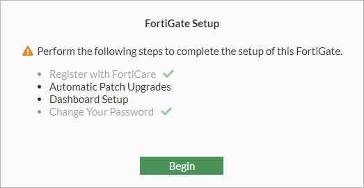
Leave everything at their default setting except for setting your password. When that process is finished you are presented with the management web interface of the FortiGate go ahead and edit a few basic things first
System Settings
Before configuring the interfaces, i’d like to make some changes to the system settings first.
Go to System -> Settings and adjust:
- Host name
- Set your desired hostname, mine is set to this format:
- WVH-FW-01 (My initials – FireWall – 01)
- Set your desired hostname, mine is set to this format:
- Time zone
- Set to your local time zone
- HTTP port
- 88
- HTTPS port
- 8443
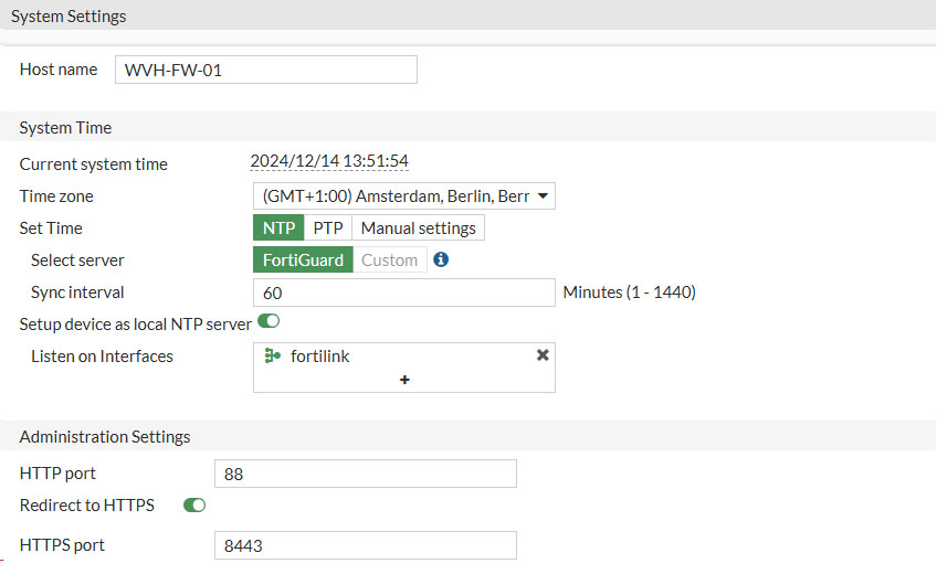
As we changed our HTTPS port we need to adjust the URL when trying to reach to web interface to: https://192.168.1.99:8443
With that out of the way, we can finally start editing the FortiGate interfaces. Beware that i might split this tutorial in two because not everyone has the whole Forti Fabric like i have and might only have a single FortiGate
Interfaces
Anyway, let’s navigate to Network -> Interfaces
Here we will be presented with all the interfaces the FortiGate has to offer. Since i have a FortiGate 60F the interfaces that are available are:
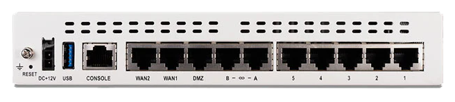
Where WAN1 is connected to my ISP and ports 1 to 5 are connected to the (hardware) VLAN Switch called internal. For good practice i want port 5 to be a dedicated management interface in case there are any issues with the internal network and i need to get management access to the FortiGate. Although it might also be possible to the Console port when using a serial cable (supplied together with the FortiGate) that would involve using the CLI and that is out of the scope of this particular tutorial.
Internal Switch
So navigate to Network -> Interfaces in the web interface of the FortiGate and click on internal and then click on Edit. This will bring up the configuration page of that particular interface (or switch in this case) called internal. There we are the presented with the physical ports (Interface members) that make up the switch. Click on the square right next to Interface members and remove internal5 from the switch. It will not be highlighted yellow anymore indicating that we have successfully deselected it. Another option is to click the cross icon of internal5 on the left hand side.

Keep in mind that you also enable Create address object matching subject, this will create an address object that we can reference later when assigning firewall policies.
Verify that you have set Administrative Access to HTTPS, HTTP and PING to make sure you don’t lock yourself out.
Now go ahead and click OK to save the changes.
Management Interface
Head over to Network -> Interfaces. There you will find that physical interface 5 has been placed out of the internal VLAN Switch as we requested and is ready to be configured as a dedicated management port

Select the internal5 interface and click on Edit.
Now we can proceed with configuring the management interface with its own IP address. Use these IP settings or substitute your own as needed.
- Role: LAN
- Address mode: Manual
- IP/Netmask: 192.168.200.1/24
- Create address object matching subnet (Enable)
- Administrative Access
- IPv4
- HTTPS, HTTP, SSH, PING, FMG-Access, FTM
- IPv4
- DHCP Server (Enable)
- Address range
- 192.168.200.100-192.168.200.150
- Netmask
- 255.255.255.0
- Address range
- DNS Server: Same as Interface IP
- Lease Time: 86400 (1 day)
Click on OK to save and activate the changes.
We now can disconnect our UTP cable from port 1 of the FortiGate and connect it to port 5. Verify that we’ve gotten an IP address in the range of 192.168.200.x. If that isn’t the case then again renew your IP in the Command Prompt in Windows.
ipconfig /renewWhen successful log back into the FortiGate on it’s newly assigned IP address https://192.168.200.1:8443.
Internet Connection
Now is a good time as any to configure the WAN connection. So head over to Network -> Interfaces once more.
Depending on the requirement of your ISP you can go three different routes here.
- Manual: You have been given a static IP address from your ISP
- DHCP: You are being assigned an IP address through DHCP
- VLAN: You are being given a static or assigned a dynamic (DHCP) IP address inside a VLAN
- PPPoE: You are being assigned a dynamic (DHCP) IP address in a PPPoE tunnel on top of a VLAN
Most European ISP’s use PPPoE (Point to Point Protocol over Ethernet) in order to assign an IP address to their customers. Like my ISP (KPN) does as well. In order to get a WAN IP address we’re going to create a new Interface (VLAN) and use WAN1 as it’s physical interface.
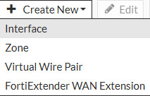
At the top of the web interface click on Create New and select Interface
Depending on the requirements of your ISP, fill in the appropriate settings. These are the requirements my ISP demands (in Dutch)
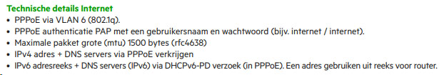
As you can see i needed to use PPPoE inside VLAN6 to get an IP address, so let’s set that up.
- Name: Give the interface a name (can be anything you’d like. Beware you cannot change this afterwards)
- I’ve set it to: KPN-Internet
- Type: VLAN
- Interface: wan1
- VLAN ID: 6
- Role: WAN
- Estimated bandwidth: 100000
- For 100Mbit Fiber connection (edit for yours)

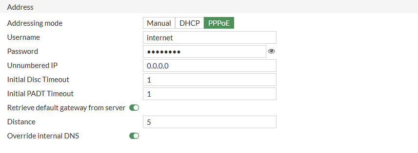
- Addressing mode: PPPoE
- Username/Password
- Fill in the username and password you’ve received from your ISP
- Mine was as instructed internet/internet
Under Administrative Access only select PING because we don’t want to manage the FortiGate from the WAN interface, only from the inside (internal (LAN) switch)
Click OK when to save the changes.
Firewall Policy
Now that we are finished setting up the interfaces it is time to configure the last step for internet packets to get flowing. And that is setting up a firewall policy. Unlike other network manufacturers I’ve been using Fortinet requires to explicitly allow traffic to flow from one interface to another. Other manufacturers like Cisco, Ubiquity by default allow all traffic which you can allow or deny by configuring access lists for example.
This makes sense since Fortinet is renowned for it’s enhanced security measures and just allowing all traffic to flow between interface defies the whole purpose of such a powerful NGFW.
But for demonstration purposes and the simple nature of this tutorial we’re going to do that anyway. We’re going to make a simple firewall policy that will allow traffic from our internal hardware switch to internet (the VLAN on top of wan1)
In the web interface of the FortiGate go to Policy & Objects and select Firewall Policy. Make sure you have Interface Pair View selected in the top right corner.
Here you will find one firewall policy and that is the Implicit Deny rule. What this rule does, if none of the above firewall policies are met, just block that traffic. Go ahead and create a new policy by clicking on Create New in the top left corner
Edit the settings like this
- Name: Give your firewall policy a recognizable name
- I’d like to do the SOURCE > DESTINATION format
- Incoming interface: Select the interface the traffic is originating from, which is the hardware switch called internal
- Outgoing interface: Select the interface the traffic is destined to, which is the KPN-Internet VLAN
- Source: Select the source address the traffic is coming from, which is the IP range of internal and is called internal range
- This object is created by selecting Create address object matching subnet in the Edit interface section like we did a few steps back
- Destination: Since we are going to the Internet, select all here
- Select which destination is allowed for our Source range
- Schedule: Always
- When do you want this rule to be active ?
- Service: Select ALL, because all services are to be allowed to the internet
- Which service (protocol) is allowed to the destination
- Action: Accept
- Accept the traffic as specified above
- NAT: Enabled
- Since most ISP’s only give out one IPv4 address we need to enable NAT to allow our internal network to communicate with the internet
Leave everything else default. That includes not enabling:
- Antivirus
- Web Filter
- DNS Filter
- Application Control
- IPS
- File Filter
- SSL Inspection
Those features will be handled in a future tutorial.
Under Log Allowed Traffic select All Sessions for the firewall to be able to log all incoming and outgoing traffic over the firewall policy we just created. Very useful for debugging purposes, also handled in a future tutorial.
Now click on OK to save and activate the firewall policy. It should look something similar to this

DNS Server
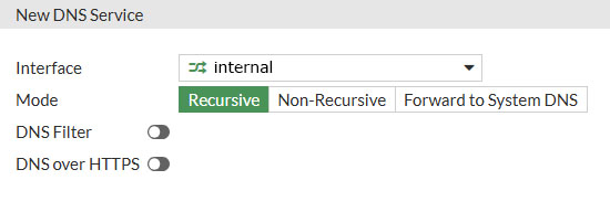
One final step we must take in order to make internet access work, is enable a DNS server on the internal interface. To do that go to Network -> DNS Servers and click on Create New under DNS Service on Interface
Under Interface select the internal interface and leave the rest of the options at default. Click OK to save
It’s time for a pad on the back. Congratulations if everything went correctly you have just realized a working internet connection from your LAN to your WAN. Let’s test that out before connecting our other Fortinet fabric members. Connect your PC to port 1 of the FortiGate and navigate to a random website.
When successful you should be presented with a webpage and also see the Bytes counter in the Firewall Policy increment as the rule Internal > Internet is being hit.

When the FortiGate is the only FortiNet device in your network you can stop here. The rest of the tutorial is about getting the other fabric members like the FortiSwitch and FortiAP’s connected to the network. In a future tutorial i dive deeper into what the FortiGate is capable of, but for now it’s just realizing basic routing to the internet from our LAN.
FortiSwitch
Now it’s time to bring out the big guns and really start building up our entire Fortinet setup. Which will include connecting the FortiSwitch and at a later stage connecting both FortiAP’s as well. But let’s start by connecting the FortiSwitch to the FortiGate first.
Interfaces
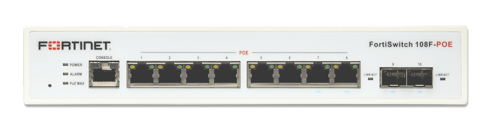
As shown by the image above the FortiSwitch 108F-FPOE has eight 1Gbit/s ports which are all PoE+ (802.3af/at) capable and is able to deliver 130W to all of these ports. I intent to use most of these ports to power both FortiAP’s, several IP camera’s and some IoT devices. That makes ports on this switch quite scarce, so i choose to utilize both SFP ports as well by buying two Ubiquity SFP RJ45 transceivers and sliding them into ports 9 and 10. Effectively expanding this 8 port switch to a 10 port switch.
It doesn’t matter to which port you connect the FortiGate to, but i choose to connect it to port 9 (which has the SFP RJ45 transceiver) You can choose any port you’d like.
FortiLink
FortiLink is the connection between the FortiGate and the FortiSwitch and takes care of the provisioning of Fortinet equipment. It should already be configured when setting up a new FortiGate. Just to be sure that it is, log back into the FortiGate. Navigate to the URL of your ForftiGate. Assuming you’ve followed this tutorials faithfully that would be connecting your PC to port 5 of the FortiGate and navigating to https://192.168.200.1:8443 in your webbrowser. On the left hand side go to WIFI & Switch Controller and click on FortiLink Interface
The most noticeable settings on this page are:
- Interface members: A and B interfaces on the FortiGate
- Notice how port A is green and connected to port 9 of the FortiSwitch
- Port B can be connected to another FortiSwitch in the future if i’d like to expand my network with a second FortiSwitch

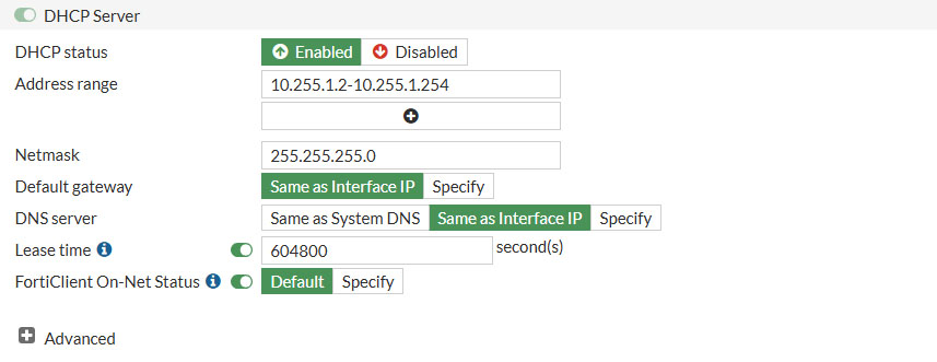
- IP/Netmask: This IP range and Netmask should already be filled in
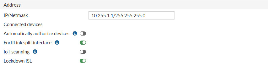
- DHCP Server: This DHCP range should already be filled in
Click Apply to update the setting and let’s move on to authorize the connected FortiSwitch
Authorize
Connect any port of the FortiSwitch you’d like to port A of the FortiGate.
On the left side of the web interface go to WIFI & Switch Controller and select Managed FortiSwitches
It might take some moments for the connected FortiSwitch to show up. When it does it is greyed out and needs to be authorized. Right click on the switch and then select Authorization -> Authorize.

The switch now it going to be provisioned and absorbed into the Fortinet Fabric, where the FortiGate is the controller to stay in Ubiquity terms.
Once the FortiSwitch comes back online, this might be a useful moment to upgrade to the latest (mature) firmware as well. Right click on the FortiSwitch and choose Upgrade. If there is an upgrade available it will say so and you can choose to upgrade to the newer firmware or proceed without. Your choice.
VLAN
Now that the FortiSwitch is operational we can create our VLANs. VLANs allow us to group together certain devices into their designated isolated network. For example, i have the following VLANs
- DATA: VLAN10
- Network segment designated for my private LAN
- GUESTS: VLAN20
- Network designated for guest users
- PRINTERS: VLAN30
- Network segment designated for printers
- IOT: VLAN40
- Network segment designated for IoT devices like IP camera’s and LoRa devices
Let’s create our first VLAN. In the FortiGate web interface go to WIFI & Switch Controller and select FortiSwitch VLANs. Then click on Create New to create your very first VLAN
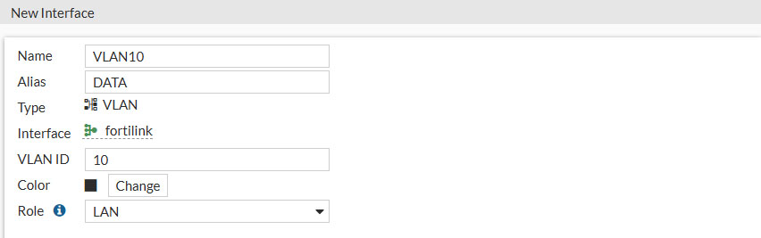
- Name: Give your VLAN a name
- Tip! name it as the VLAN ID. e.g. VLAN10 (since this cannot be changed upon committed)
- Alias: Give your VLAN an alias
- This can be changed after being committed. I’ve named mine DATA
- VLAN ID: Set your VLAN ID, let’s set this to 10. Can be every number between 1 and 4094
- Role: LAN
- Addressing mode: Manual
- IP/Netmask
- Enter the desired IP/Netmask of your VLAN
- I’ve set mine to: 192.168.10.1/24
- .10.x indicating it’s VLAN 10
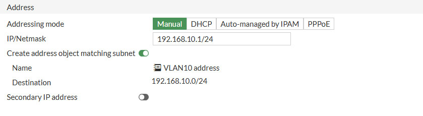
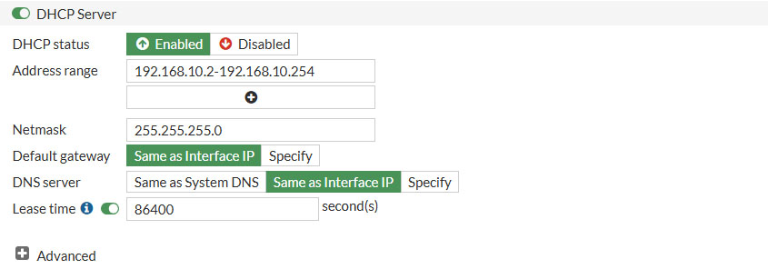
- DHCP Server
- Address range
- 192.168.10.2-192.168.10.254
- Netmask
- 255.255.255.0
- DNS server
- Same as interface IP
- Lease time
- 86400 (1 day)
- Address range
- Device detection
- Enable (to be able to detect devices in this VLAN)
Under Administrative Access only enable PING and under network enable Device Detection
Assigning VLANs to Ports
We are really making headway here. Thus far we have created a VLAN and now it’s time to assign that VLAN to a port. VLANs can be assigned in two ways
- Access Ports: Choose this option if your connected device is VLAN unaware and you’d like to assign one VLAN per port
- I could choose ports 1 to 4 to be Access Ports and assign VLAN10 to these port. Which will make all of these ports members of VLAN10
- Tagged Ports: Choose this option if your connected device is VLAN aware and you’d like assign one or more VLANs per port
- I could choose ports 5 to 8 to be Tagged Ports and assign multiple VLANs to these ports. Which will make the ports VLAN tagging aware and will place the VLAN tagged members in their desired VLAN.
A good example is IP camera’s. They often don’t support VLAN tagging, so they only allow you to set it’s IP address. Creating an access port for this camera with VLAN40 will make the IP camera a member of VLAN40 even though the camera itself isn’t aware it’s being placed in a specific VLAN.
VLAN aware devices (tagging) like FortiAP’s do have the option the pass along the VLAN tags as they can be members of multiple VLANs at once. Most access points can send out multiple SSID’s and this would give us the option to create one SSID for VLANx and another SSID for VLANy. Separating these network. But more on that later.
With this little piece of knowledge we can start assigning VLANs to ports. On the left hand side go to WIFI & Switch Controller and select FortiSwitch Ports
In this part of the web interface, we are presented with a table that lists all the physical ports offered by the FortiSwitch. In my case, these include 8 Power over Ethernet (PoE) ports and 2 Small Form-factor Pluggable (SFP) ports. The column header that we are currently interested in is Native VLAN. Native VLAN refers to the term used by Fortinet for Access Ports, as discussed previously. By default, these ports are set to _default_fortlilink (_default). More information on this topic will be provided in a later tutorial. For now, let’s change the Native VLAN of each port to the one we created earlier (VLAN 10). To do so, click on the Native VLAN column and select the port you want to assign the VLAN to; it should highlight yellow and allow you to edit its configuration by clicking the pen icon. Change the assigned VLAN to VLAN10 and confirm your changes by clicking Apply.
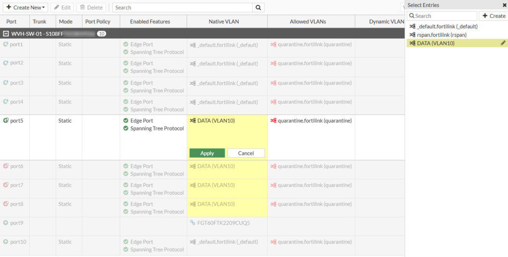
Verify if VLAN10 is successfully assigned to the selected ports. Then plug in your PC in one of the edited ports and verify that you’ve received an IP address
Firewall Policy
Like before, we have to create a firewall policy once again. Allowing traffic from VLAN10 to travel to the destinations we specify. For now i’m going to allow all traffic from VLAN10 address to the internet. Go to Policy & Objects -> Firewall Policy and click on Create New at the top.
Like before give the policy a descriptive name and select the following options:
- Incoming Interface: DATA (VLAN10)
- Outgoing Interface: KPN-Internet
- Source: VLAN10 address
- Destination: all
- Service: ALL
- NAT: Enabled
- Leave everything else, click OK to confirm
When done you have something resembling this policy

DNS Server
One final step we must take in order to make internet access work, is enable a DNS server on the newly created VLAN. To do that go to Network -> DNS Servers and click on Create New under DNS Service on Interface
Under Interface select the VLAN we previously created and leave the rest of the options at default. Click OK to save

Now it’s time to verify if we can access the internet from the newly configured FortiSwitch. Connect your PC to port 5 (or ports 6-8, as all of these have been assigned VLAN10 in our example) on the FortiSwitch and renew your IP address. This should result in an IP address within the range of VLAN10, which is 192.168.10.x. Once you’ve obtained a new IP address, opening a web browser should allow you to access the internet successfully.
FortiAP
The final piece of the Fortinet Fabric puzzle is to connect the FortiAP to the FortiSwitch. Since it is a PoE switch this will also supply power to the FortiAP. On the FortiSwitch i’m intending to use ports 1 and 2 to connect my FortiAP’s to.

Management VLAN
When first setting up the FortiAP, I encountered some initial confusion because the FortiAPs require their own Native VLAN to operate and obtain an IP address. Let’s refer to this VLAN as the Management VLAN (MGMT VLAN) for clarity and consistency.
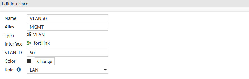
Let’s create this VLAN so that we can adopt the FortiAP’s into the network. Go to WIFI & Switch Controller and select FortiSwitch VLANs. Then click on Create New and edit the settings.
- Name: VLAN50
- Alias: MGMT
- Type: VLAN
- VLAN ID: 50
- Role: LAN
- Addressing mode: Manual
- IP/Netmask: 192.168.50.1/255.255.255.0
- Create address object matching subnet: Enable
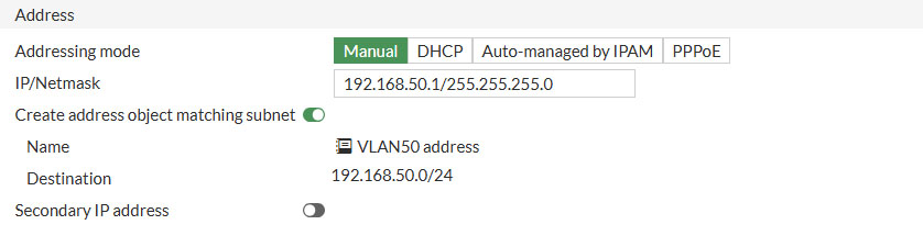
The only thing that is different from creating a regular VLAN and which is crucial for getting the FortiAP’s recognized by the fabric is dat you select Security Fabric Connection.

- DHCP status: Enable
- Address range: 192.168.50.100-192.168.50.150
- Netmask: 255.255.255.0
- DNS server: Same as Interface IP
- Lease time: 86400 (1 day)

Once we’ve configured everything, hit OK to save the changes
Assigning MGMT VLAN to Ports
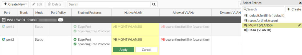
Like we did before we are now going to assign the Native VLAN to the ports where we intent to connect the FortiAP’s to. As i have two FortiAP’s i need to assign the MGMT VLAN to the Native VLAN of two ports, I’ve decided to use ports 1 and 2 of the FortiSwitch for that purpose.
Head over to WIFI & Switch Controller and select the port(s) you want to connect the FortiAP to, then hover over the entry beneath the column Native VLAN and click the pen icon. On the right side under Select Entries, select the MGMT (VLAN50) entry and save by clicking on Apply
At this point we can go ahead and connect the FortiAP’s to their designated ports. That means in my situation connecting LAN1 of the FortiAP’s to port 1 and 2 of the FortiSwtich. In a few moments the PoE autosensing will detect that there is an PoE capable device connected to the ports and will start to supply power to them. The FortiAP’s will power up, keep in mind this might take some time.
Authorize
When the FortiAP’s are fully power up, we can start to adopt them into the Fortinet Fabric. Go to WIFI & Swtich Controller in the web interface and select Managed FortiAP’s. Here we can adopt the FortiAP by selecting the FortiAP and clicking on Authorization -> Authorize
The FortiAP’s are being provisioned in the background and most likely are going to reboot. When they are rebooting let’s configure some other things needed for the FortiAP’s to operate as intended, like creating a FortiAP Profile.
FortiAP Profile
FortiAP profiles are used to define the behavior of the connected FortiAP’s. In a FortiAP Profile for example you can define on which channels to operate, set the maximum output power and so on. By default there is a FortiAP Profile already created called FAP231F-default (yours may differ, or maybe absent all together)
First we need to set our country by going to WiFi & Switch Controller -> WiFi Settings. Here we change the WiFi country/region to your location
Then go to WIFI & Switch Controllers and select FortiAP Profiles. If there isn’t a profile already present, just hit Create New to create a fresh one, or just select the default profile called FAP231F-default and hit Edit
Like i mentioned before, this is the page where we’re going to define the mode of operation. For simplicity reasons i will leave as much as possible at default setting, only the most necessary settings are being mentioned. In a future blog post i will dive deeper into optimizing the wireless settings.
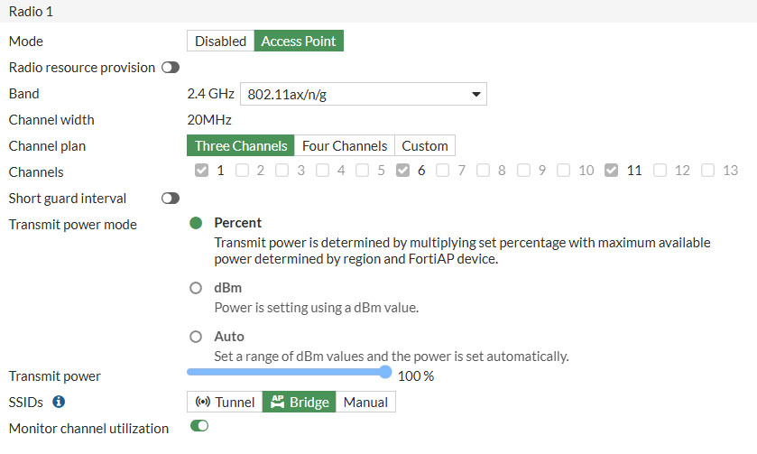
In the default FortiAP Profile we’re going to change a couple of things.
- Country / Region
- Should already been set to your country/region

- Radio 1: This is the 2.4Ghz radio of the FortiAP 231F
- Mode: Access Point
- Channel: Three Channels
- SSID: Bridge
- Radio 2: This is the 5Ghz radio of the FortiAP 231F
- Mode: Access Point
- Channel width: 40Mhz (set to 80Mhz for more speed)
- SSID: Bridge

- Radio 3: This is the dedicated monitor that will scan the RF surroundings
With the FortiAP Profile configured, we can move on by creating and assigning a SSID to the FortiAP’s
SSID
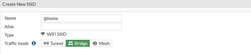
The SSID is the name you will give to your wireless network. This will be the name which will show up when you’re looking for wireless networks on your client devices. I’ve called mine @home but you can choose whatever SSID you’d like.
In the web interface go to WIFI & Switch Controllers and select SSID. Click on Create New and select SSID to create a SSID for your network. There we need to define a few things, though not all settings need to be filled in. For now, just focus on these settings:
- Name: Give your SSID a descriptive name
- Traffic mode: Bridge
- This is important in order to connect your wireless network to your LAN (VLAN10)
- SSID: The name (SSID) the FortiAP will broadcast
- This is the name (SSID) your client devices will connect to
- Security mode: WPA2 Personal
- The level of encryption of your wireless network
- Passphrase: The passphrase that let’s you connect to your wireless network
- Needs to be at least 8 characters

- Optional VLAN ID: 10
- Set this to the VLAN ID of our LAN (VLAN10) we’ve created in a previous step

The hit OK to save and activate
Allow VLANs to Ports
Now that we have configured all of the components that make up a Fortinet network, the only thing that is left is to allow the VLANs to pass through the FortiSwitch ports. Remember the Native VLAN we’ve configured in a previous step which the FortiAP is currently connected to is just for management purposes only so that the FortiAP can get it’s IP address and is able to receive management traffic from the FortiGate. We need to allow VLAN 10 (our LAN network) to be allowed to pass through that same port, which is conveniently called Allowed VLANs
Go to WIFI & Switch Controllers and select FortiSwitch Ports. Here we still only have configured our Native VLANs for both our FortiAP’s. Right next to the Native VLAN column is the Allowed VLANs column which basically means, which VLANs do you like (allow) to pass through this port as well. In our case that would be VLAN10 since that is our LAN network.
So once more right click to select the port under Allowed VLANs, hover over the entry beneath Allowed VLANs until the pen icon appears and click on it. On the right hand side under Select Entries besides the default entry called quaraintine.fortilink (quarantine) also select DATA (VLAN10) and hit Apply to confirm

And that’s it, you’re finished.
Conclusion
You should now be able to login to your wireless network and get internet access. Although this is a very basic configuration it lays the basics for implementing more advanced configuration options in future blog posts, like creating more sophisticated firewall rules and using the filters Fortinet is renowned for.
More on that later, for now enjoy your newly created Fortinet network and leave your questions in the comments below.
PayPal
If you like my work, please consider supporting.